Trebuchet – The First Fling

19 11 2008

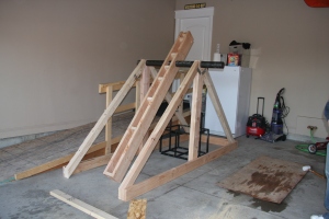
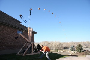
We had our first test of the trebuchet with the full 600+ lbs of concrete, and well it a huge… Well just see for yourself!  This was the very first toss!

trebuchet-sequence2

Photo sequence provided by Irotras! Thanks for the awesome shots!

I don’t know how far it went exactly because we were so busy tossing the next pumpkin, but by my estimates the really heavy pumpkins (about 15+ lbs) were going about 100 ft. and the small pumpkins (about 6-8 lbs) were going about 200 ft.  That’s good, but it can be better!  One thing that was clearly evident in watching the trebuchet is that there is too much friction in the throwing arm and main axle joint.

I have some video that was taken with a real video camera, and once clean it up I will post that.

I would like to thank every one that helped me out on this project, specially my wife for being understanding and listening to the days and day of technobabel.


Trebuchet – Throwing Arm

11 11 2008

So in explaining on how to size the primary axle, I realized something.  The same force that the primary axle experiences will also be experienced by the secondary axle!  This is bad, considering that I was planning on using something a lot smaller on the secondary axle.

However, this is not a complete disaster!  We had a couple of different options.

  • Resize the axle
  • make the axle strong (I don’t know how exactly)
  • or distribute the forces closer to the edges

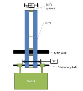
So that’s what we did!  Instead of having the two 2×8’s right next to each other we decided that we would put a 2×4 in between the board in order to space out the forces that the 2×8’s are putting on the secondary axle.

img_7873

throwing-arm-adjustment1

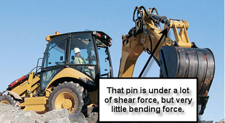
The forces are acting on the basket, throught the axle to the throwing arm.  The closer we bring the 2×8’s to the basket arms the less of a moment arm there is, which means less bending.  Just think for a minute.  We’ve all seen those large cat machines and all of those joints are made in a similar fashion to how we are making the basket joint.  If we look at the figure below the pin there is a tremenous amount of forces on that pin, but it completely in shear forces, and not bending.  It’s a lot easier to deal with shear forces, than it is to deal with bending forces.

So that what we did by separtating the beam and distributing the forces.

Other Resources

Trebuchet Design

Cement Blocks

Counterweight

Sizing the Axle (Part 1)

Sizing the Axle (Part 2)

A-Frames

Car Throwing Trebuchet

Cool Trebuchet Pictures

The bucket


Trebuchet – Cement Blocks

10 11 2008

This weekend we had a strong surge and are very close to completing the Trebuchet!  A very special thanks to all of the those who helped!

In order to reach our goal of throwing a 6 lbs pumpkin the length of a football field we need to have a counterweight 100 times bigger.  So that means we need 600lbs of something.  Well, we looked around but couldn’t find anything that was dense enough, cheap enough.  Lead would be ideal, but where do we get 600 lbs of lead, and who wants to work with lead anyway?

So we went with the next best thing!  CEMENT!  According to the McGraw-Hill Encyclopedia of Science and Technology, “Volume generally assumed for the density of hardened concrete is 150 lb/ft^3 or 2400 kg/m^3.”

Since we need 600 lbs we need a volume of

600 lbs/150lbs/ft^3 = 4 ft^3

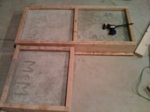
of cement.  This translates into 1.58 ft or approximately  20 inches on each side.   Our cement blocks are going to be 21.5 inches wide, and 19.5 deep, and 4 inches high.  We did this so the the cement blocks wouldn’t interfere with the throwing arm when the trebuchet arm is cocked back.   It will make sense once I get a picture up of that.  Anyway… here are the remain 3 blocks of concrete that are needed to make up the counterweight.

cement-blocks

Other Resources

Trebuchet Design

Cement Blocks

Counterweight

Sizing the Axle (Part 1)

Sizing the Axle (Part 2)

A-Frames

Car Throwing Trebuchet

Cool Trebuchet Pictures

The bucket


Trebuchet – Sizing the Axle (Part 2)

7 11 2008

Ok, so in Sizing the Axle (Part 1) we found out how to determine the forces that act on the main axle.  We want to determine the appropriate size for the main axle so that it doesn’t deform the main axle.

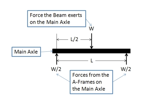
The first step is to draw a free body diagram of the forces acting on the main axle.  Figure 1shows the two forces from the A-Frame acting on the axle (pointing up) and the force from the throwing arm acting on the main axle (point down).  The Force the Beam exerts on the axle is the 2048 lbs force that we calculated in Sizing the Axle (Part 1).  For a quick reminder

W = 2*W*(1-cos(θ)) = 2048lbs.
beam-equations

Figure 1

So the axle will fail if it gets too much stress in it.  So we need a way to determine the stress inside the axle.  From Machinery’s Handbook V27 page 261 we can see that the stress in a beam under this type of loading can be found by

stress = -WL/4Z     (I)

where

W is the load on the beam.

L is the length of the beam (in our case

Z is the section modulus of the cross-section of the beam

Wait ….what?  What does that mean?  That doesn’t mean much to me.  However it’s easy to find out.

Z is determined by

Z= I/c    (2)

where

I is the moment of Inertia.

c is the distance from the neutral axis to the extreme fiber

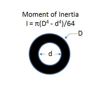
The moment of inertia can be found using integrals, but we are just going to find it in a book.  See figure 2.
moment-of-inertia

Figure 2

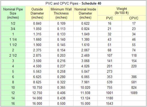
So we need to know the deminsions of the axle, but that’s what we are trying to find out.  Well, it can get pretty difficult to find out what those values are directly, so I suggest picking a size and them following this guide.  We were lucky enough to find some pipe dumpster diving.  We found some schedule 40 3″ pipe. Now 3″ pipe is just a name. The actual dimensions are as follows

So now knowing the inner and outter dimension we can determine the moment of inertia for our scavenged pipe.

I = π(D^4-d^4)/64 = π(3.5^4 – 3.068^4)/64 = 3.129in^4

and in this case the distance from the neutral axis to the outer most edge is

c = D/2 = 1.75 in

so

Z = I/c = 3.129/1.75 = 1.788 in^3

We know have all of the information to calculate the stress in our axle.

Stress = -WL/4Z = -2100*32/4*1.788 =~ 9400 lbs/in^2 or 9400 psi.

Ok, so we found out what the stress is in the pipe. The next step depends on the material that your pipe is made of.  We know that it is some type of steel, but there are a lot of different types of steel out there each with there own mechanical properties.  So we are going to use a very low grade steel.  We are going to assume that the allowable bending stress is 30,000 psi.

So the stress in the pipe is much less than 30,000 psi so we should be good, but we need to calculate what the safety factor is.

Safety Factor = Allowable bending stress/ calculated bending stress = 30,000/9400 = ~3

I must say that the force on the beam needs to be readjusted to include the mass from the beam.  However, we don’t have the exact number but we do have an estimate.   I went ahead and recalculated the force and it comes out to be about 2400 lbs (rounded up).

So the stress comes out to be

Stress = -WL/4Z = -2100*32/4*1.788 =~ 9400 lbs/in^2 or 10800 psi.

And our new Safety Factor is

S.F. = 30000/10800 = ~ 2.7

That’s still is pretty strong.  It’s important to have a large safety factor because you can’t account for everything!  So be conservative in your calcuations.  If your calculations don’t have a large enough S.F.  pick a larger pipe size and start again, or use a very strong type of steel.

Other Resources

Trebuchet Design

Cement Blocks

Counterweight

Sizing the Axle (Part 1)

Sizing the Axle (Part 2)

A-Frames

Car Throwing Trebuchet

Cool Trebuchet Pictures

The bucket


Trebuchet – Sizing the Axle (Part 1)

30 10 2008

This is a very important part to building a trebuchet!  To big and you weaken the swing arm, to small and you will have a damaged axle.

Since we are going to be swinging 600 lbs around we wanted to make sure that it wasn’t going to fail.  We also wanted to make sure that AS MUCH of the energy is transfered to the pumpkin and not the axle.  To do this you just need a really rigid axle, but how do you size it?

First thing is to find out how much energy you gain by droping the counterweight.  So, we have a counterweight with mass M.  We also have a beam with mass B.  For simplicity I am going to say that the beam, though it’s size is going to be considerable and should be considered for a complete analysis, is negligible.  I am also going to simplify the model even further by saying that the weight is a fixed weight on the swing arm itself.  This reduces one degree of freedom and simplifies the problem immensely.

What we are actually looking at is now just a simple pendulum.  This isn’t a true representation, but should get us in the right ball park.

Ok the force on the axle as it swing will be the centripetal force acting on it. We know that

F=ma  (1)

but that is for a linear force.  Since our weight is swinging we want angular, and that where the centripetal acceleration comes in.

a = v^2/r  (2)

a = acceleration

v = velocity

r = radius

Substituting 2 into 1 yeilds

F=m*v^2/r  (3)

We still have too many variables to use the equation directly.  We don’t know the velocity, yet.  We do know that velocity is dependent on height, and gravity.  We know that

1/2 * mv^2 = mgh

Since the mass doesn’t change the mass cancels out.

1/2 * v^2 = g*h

solving for v^2 (normally you would want to solve for v not v^2, but it makes sense. Trust me!)

v^2 = 2*g*h (4)

Ok, we are getting somewhere now!  Sub 4 into 3

F= m*(2*g*h)/r = 2mgh/r   (5)

Now this is better, this is something we can work with.  However, we can simplify this even further since h, the height is dependant on the angle of the trebuchet and the length from the axle to the counterweight.

From magic, or voodoo (whatever you wish) you get that

h = r*(1-cos(Θ)) (6)

So we can sub 6 into 5

F = 2*m*g*(r*(1-cos(Θ))/r = 2*m*g*(1-cos(Θ))

So

F= 2*m*g*(1-cos(Θ))

or

F = 2W(1-cos(Θ))

So, in my case, I am using a 600 lbs counterweight, and ideally we will be dropping it 135 degrees (measured from the resting position).

So

F = 2*600*(1-cos(135deg))=2048lbs

That’s a pretty significant force.  If you were able to do a full rotation your axle would be experiencing 4 times the weight of the counterweight.  That’s good to remember when designing your trebuchet!

Other Resources

Trebuchet Design

Cement Blocks

Counterweight

Sizing the Axle (Part 1)

Sizing the Axle (Part 2)

A-Frames

Car Throwing Trebuchet

Cool Trebuchet Pictures

The bucket