Ok, so in Sizing the Axle (Part 1) we found out how to determine the forces that act on the main axle. We want to determine the appropriate size for the main axle so that it doesn’t deform the main axle.
The first step is to draw a free body diagram of the forces acting on the main axle. Figure 1shows the two forces from the A-Frame acting on the axle (pointing up) and the force from the throwing arm acting on the main axle (point down). The Force the Beam exerts on the axle is the 2048 lbs force that we calculated in Sizing the Axle (Part 1). For a quick reminder
W = 2*W*(1-cos(θ)) = 2048lbs.

Figure 1
So the axle will fail if it gets too much stress in it. So we need a way to determine the stress inside the axle. From Machinery’s Handbook V27 page 261 we can see that the stress in a beam under this type of loading can be found by
stress = -WL/4Z (I)
where
W is the load on the beam.
L is the length of the beam (in our case
Z is the section modulus of the cross-section of the beam
Wait ….what? What does that mean? That doesn’t mean much to me. However it’s easy to find out.
Z is determined by
Z= I/c (2)
where
I is the moment of Inertia.
c is the distance from the neutral axis to the extreme fiber
The moment of inertia can be found using integrals, but we are just going to find it in a book. See figure 2.

Figure 2
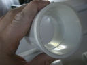
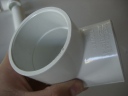
So we need to know the deminsions of the axle, but that’s what we are trying to find out. Well, it can get pretty difficult to find out what those values are directly, so I suggest picking a size and them following this guide. We were lucky enough to find some pipe dumpster diving. We found some schedule 40 3″ pipe. Now 3″ pipe is just a name. The actual dimensions are as follows

So now knowing the inner and outter dimension we can determine the moment of inertia for our scavenged pipe.
I = π(D^4-d^4)/64 = π(3.5^4 – 3.068^4)/64 = 3.129in^4
and in this case the distance from the neutral axis to the outer most edge is
c = D/2 = 1.75 in
so
Z = I/c = 3.129/1.75 = 1.788 in^3
We know have all of the information to calculate the stress in our axle.
Stress = -WL/4Z = -2100*32/4*1.788 =~ 9400 lbs/in^2 or 9400 psi.
Ok, so we found out what the stress is in the pipe. The next step depends on the material that your pipe is made of. We know that it is some type of steel, but there are a lot of different types of steel out there each with there own mechanical properties. So we are going to use a very low grade steel. We are going to assume that the allowable bending stress is 30,000 psi.
So the stress in the pipe is much less than 30,000 psi so we should be good, but we need to calculate what the safety factor is.
Safety Factor = Allowable bending stress/ calculated bending stress = 30,000/9400 = ~3
I must say that the force on the beam needs to be readjusted to include the mass from the beam. However, we don’t have the exact number but we do have an estimate. I went ahead and recalculated the force and it comes out to be about 2400 lbs (rounded up).
So the stress comes out to be
Stress = -WL/4Z = -2100*32/4*1.788 =~ 9400 lbs/in^2 or 10800 psi.
And our new Safety Factor is
S.F. = 30000/10800 = ~ 2.7
That’s still is pretty strong. It’s important to have a large safety factor because you can’t account for everything! So be conservative in your calcuations. If your calculations don’t have a large enough S.F. pick a larger pipe size and start again, or use a very strong type of steel.
Other Resources